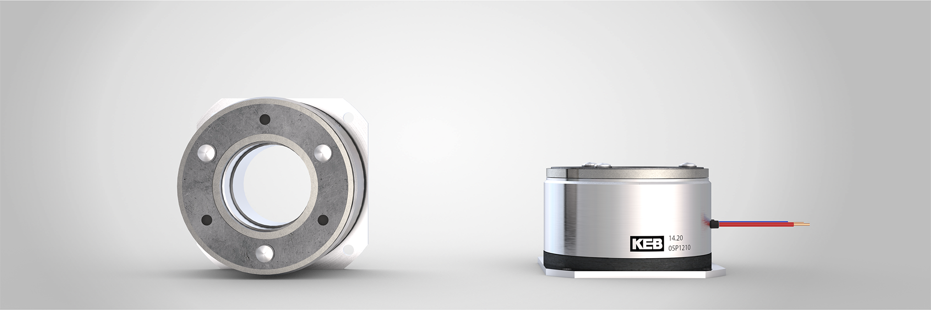
STANDARD PERMANENT MAGNET BRAKE
COMBIPERM P1
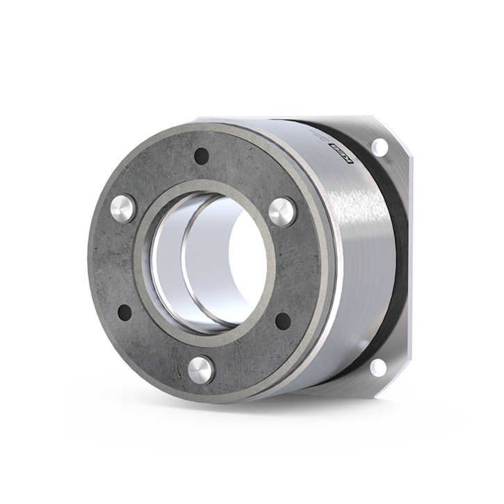
The COMBIPERM P1 is a powerful permanent magnet brake with a frictionally engaged, backlash-free effect. On request, the brake can also be manufactured in an HRE-free version. The use of HRE-free magnetic materials reduces dependence on critical resources and helps to create more resilient supply chains.
In the energised state, the magnetic field of the permanent magnet is cancelled and the connected component can rotate without residual torque. In the event of an emergency stop or if the power is switched off, the safety brake engages, brakes and holds the drive safely in position. Thanks to the short switching times and the compact design, these brakes are ideal for servo motors and the medical industry.
Torque range of 0.1 Nm to 194 Nm.
What are the specifications?
What are my options?
Where are e.g. the 3D models?
Where is this brake used?
Highlights
- 11 sizes
- Currently available in 6 sizes in a version without heavy rare earths
(1.4 – 49 Nm, with more to follow) - Backlash free
- Frictional engagement
- Release without residual torque
- ISO class F in accordance with VDE 0580
- cCSAus certification
- Designed for S1 operation or 100 % duty cycle
- Up to ten million switching cycles as standard
- Up to 10,000 rpm
- Standard voltage 24V

An interesting option
COMBIPERM P1 without heavy rare earths
By avoiding the use of heavy rare earths (HREs), the COMBIPERM P1 offers both economic and environmental benefits. This is because material costs can be reliably calculated, and dependence on the often volatile raw materials market and geopolitical changes is reduced. As the mining and processing of heavy rare earths such as dysprosium or terbium are energy- and resource-intensive, the HRE-free COMBIPERM P1 can also help to reduce CO₂ emissions. The functional advantages of the permanent magnet brake are, of course, retained.
The COMBIPERM P1 without heavy rare earths will be available as a prototype from the end of Q1 2027 and in series production from Q2 2027. Initially, it will be available in sizes 02, 03, 05, 06, 07 and 08. Customised designs can also be accommodated.
Variants

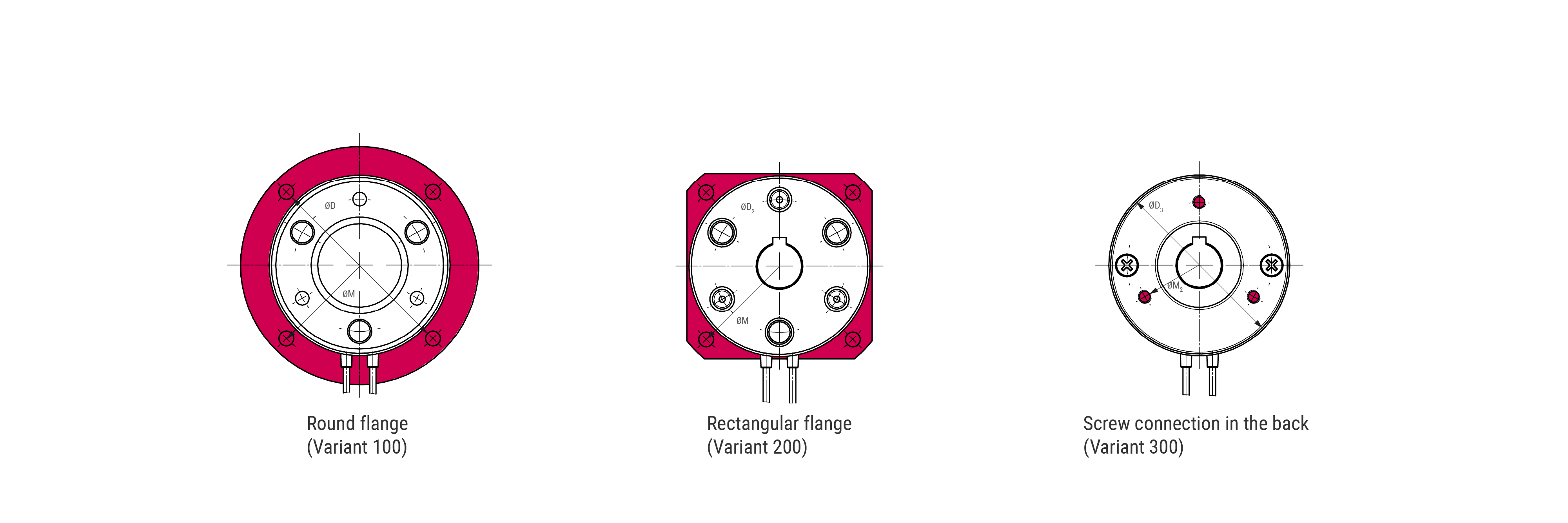
In the event of a round assembly space or round bearing plate on which the COMBIPERM P1 is to be mounted, a version with a round flange can be supplied (Variant 100).
The permanent magnet brake is screwed into the motor through the flange.

The rectangular flange design of the COMBIPERM P1 is particularly suitable for angular assembly spaces (Variant 200).
The permanent magnet brake is screwed into the motor through the flange.

If the COMBIPERM P1 is to be installed in an extremely small assembly space, we recommend choosing the screw connection at the back (Variant 300).
This means that no additional flanges are needed for the screw connection.
The bore hole pattern, threaded hole diameter, threaded hole depth and the number of threaded holes can be adapted to the customer’s requirements.
TECHNICAL DATA
| Size | Rated torque M2 [Nm] | Mdm in 120 [Nm] | Standard power P [W] | D [mm] | D2 [mm] | D3 [mm] | M* [mm] | M2* [mm] | L [mm] | L2 [mm] | L3 [mm] | dmax [mm] |
|---|---|---|---|---|---|---|---|---|---|---|---|---|
| 0A | 0.15 | 0.1 | 3 | - | - | 18 | 15.2 | - | - | - | 20.75 | 3 |
| 01 | 0.5 | 0.3 | 8 | 39 | 32 | 28 | 33.5 | 22 | 21.9 | 23.9 | 28.9 | 6 |
| 02 | 1.4 | 0.8 | 10 | 45 | 34 | 32.2 | 38 | 23 | 23.75 | 25.75 | 33.75 | 8 |
| 03 | 2.7 | 1.8 | 11 | 54 | 42 | 41 | 47 | 28,5 | 25.25 | 27.85 | 37.25 | 12 |
| 04 | 3.5 | 2.5 | 11 | 60 | 45 | 42 | 52 | 34 | 28.6 | 32.1 | 40.9 | 12 |
| 05 | 6.1 | 4 | 12 | 65 | 53 | 51.5 | 58 | 40 | 31.7 | 34.7 | 43.7 | 15 |
| 06 | 12 | 8 | 18 | 80 | 66 | 64 | 72 | 49 | 31 | 34.5 | 46 | 18 |
| 07 | 24 | 15 | 24 | 100 | 83 | 80.8 | 90 | 63 | 34.7 | 38.7 | 54.7 | 25 |
| 08 | 49 | 32 | 26 | 125 | 103 | 101 | 112 | 78 | 40.45 | 45.45 | 65.45 | 30 |
| 09 | 96 | 65 | 40 | 150 | 128 | 126 | 137 | 106 | 45.5 | 51.5 | 75.5 | 40 |
| 10 | 194 | 115 | 50 | 190 | 163 | 161 | 175 | 135 | 52.5 | 59.5 | 90.5 | 50 |
Keyway according to DIN 6885-1
ISO class F (optional H possible)
| Größe | WR0,1 / rpm | WR0,1 / kgm2 | WR0,1 / kJ | nmax / rpm | nBmax / rpm | Armature element 110 J / 10-4 kgm2 | Armature element 120/130 J / 10-4 kgm2 | t1_dc / ms 1) | t2 / ms 2) |
|---|---|---|---|---|---|---|---|---|---|
| 01 | 3000 | 0.001 | 200 | 10000 | 6000 | 0.01 | 0.013 | ≤ 9 | ≤ 10 |
| 02 | 3000 | 0.001 | 300 | 10000 | 6000 | 0.014 | 0.021 | ≤ 12 | ≤ 20 |
| 03 | 3000 | 0.001 | 410 | 10000 | 6000 | 0.045 | 0.068 | ≤ 15 | ≤ 40 |
| 04 | 3000 | 0.001 | 410 | 10000 | 6000 | 0.078 | 0.11 | ≤ 18 | ≤ 45 |
| 05 | 3000 | 0.001 | 580 | 10000 | 6000 | 0.122 | 0.18 | ≤ 20 | ≤ 50 |
| 06 | 2000 | 0.0015 | 890 | 10000 | 6000 | 0.37 | 0.54 | ≤ 30 | ≤ 70 |
| 07 | 2000 | 0.004 | 1290 | 10000 | 6000 | 1.15 | 1.66 | ≤ 30 | ≤ 90 |
| 08 | 2000 | 0.0120 | 2900 | 10000 | 6000 | 4 | 5.56 | ≤ 35 | ≤ 135 |
| 09 | 2000 | 0.036 | 6200 | 8000 | 4800 | 11.5 | 16 | ≤ 40 | ≤ 200 |
| 10 | 2000 | 0.1 | 13000 | 8000 | 4800 | 39 | 53 | ≤ 100 | ≤ 240 |
1) Time from switching off the current until reaching 0,9 M2N.
2) Disengagement time from power-on to the beginning of the torque drop.
| Size | Rated torque M2 [Nm] | Mdm in 120 [Nm] | Standard power P [W] | Weight [kg] | Air gap [mm] | Max. Air gap [mm] |
|---|---|---|---|---|---|---|
| 0A | 0.15 | 0.1 | 3 | |||
| 01 | 0.5 | 0.3 | 8 | 0.1 | 0.15 | 0.25 |
| 02 | 1.4 | 0.8 | 10 | 0.1 | 0.15 | 0.25 |
| 03 | 2.7 | 1.8 | 11 | 0.2 | 0.15 | 0.35 |
| 04 | 3.5 | 2.5 | 11 | 0.25 | 0.15 | 0.35 |
| 05 | 6.1 | 4 | 12 | 0.35 | 0.2 | 0.45 |
| 06 | 12 | 8 | 18 | 0.55 | 0.3 | 0.55 |
| 07 | 24 | 15 | 24 | 0.85 | 0.3 | 0.7 |
| 08 | 49 | 32 | 26 | 1.6 | 0.35 | 0.7 |
| 09 | 96 | 65 | 40 | 2.9 | 0.4 | 0.8 |
| 10 | 194 | 115 | 50 | 5.4 | 0.5 | 1.1 |
Storage temperature: -25...55 °C
Transport temperature: -25...60 °C
Operating temperature: optional -40...+120 °C
| Size | Rated voltage (-10%/+6%) | Power at +20°C und UN | Current at +20°C und UN (±7%) | Current at +120°C und UN (±7%) | Resistance at +20°C (±7%) | Resistance at +120°C (±7%) | Inductance in a closed system |
|---|---|---|---|---|---|---|---|
| UN / V | P20 / W | I20 / A | I120 / A | R20 / Ω | R120 / Ω | Lm / H | |
| 0AP1 | 12 | 3 | 0.25 | 0.18 | 48.00 | 67.15 | 0.3 |
| 24 | 3 | 0.13 | 0.09 | 192.00 | 268.61 | 1.2 | |
| 01P1 | 10 | 8 | 0.80 | 0.57 | 12.50 | 17.49 | 0.06 |
| 12 | 8 | 0.67 | 0.48 | 18.00 | 25.18 | 0.1 | |
| 24 | 8 | 0.33 | 0.24 | 72.00 | 100.73 | 0.4 | |
| 48 | 8 | 0.17 | 0.12 | 288.00 | 402.91 | 1.5 | |
| 02P1 | 12 | 10 | 0.83 | 0.60 | 14.40 | 20.15 | 0.15 |
| 24 | 10 | 0.42 | 0.30 | 57.60 | 80.58 | 0.5 | |
| 48 | 10 | 0.21 | 0.15 | 230.40 | 322.33 | 2.3 | |
| 03P1 | 12 | 11 | 0.92 | 0.66 | 13.09 | 18.31 | 0.2 |
| 24 | 11 | 0.46 | 0.33 | 52.36 | 73.26 | 0.7 | |
| 48 | 11 | 0.23 | 0.16 | 209.45 | 293.03 | 2.5 | |
| 196 | 11 | 0.06 | 0.04 | 3492.36 | 4885.82 | 43 | |
| 200 | 11 | 0.06 | 0.04 | 3636.36 | 5087.27 | 46 | |
| 205 | 11 | 0.05 | 0.04 | 3820.45 | 5344.82 | 31 | |
| 04P1 | 24 | 11 | 0.46 | 0.33 | 52.36 | 73.26 | 0.8 |
| 05P1 | 9 | 12 | 1.33 | 0.95 | 6.75 | 9.44 | 0.15 |
| 12 | 12 | 1.00 | 0.71 | 12.00 | 16.79 | 0.25 | |
| 24 | 12 | 0.50 | 0.36 | 48.00 | 67.15 | 1 | |
| 40 | 12 | 0.30 | 0.21 | 133.33 | 186.53 | 2.6 | |
| 48 | 12 | 0.25 | 0.18 | 192.00 | 268.61 | 4 | |
| 90 | 12 | 0.13 | 0.10 | 675.00 | 944.33 | 14.5 | |
| 205 | 12 | 0.06 | 0.04 | 3502.08 | 4899.41 | 67 | |
| 06P1 | 12 | 18 | 1.50 | 1.07 | 8.00 | 11.19 | 0.2 |
| 18 | 18 | 1.00 | 0.71 | 18.00 | 25.18 | 0.5 | |
| 24 | 18 | 0.75 | 0,54 | 32.,00 | 44.77 | 0.9 | |
| 48 | 18 | 0.38 | 0,27 | 128.00 | 179,.07 | 3.5 | |
| 90 | 18 | 0.20 | 0,14 | 450.00 | 629.55 | 11 | |
| 105 | 18 | 0.17 | 0,12 | 612.50 | 856.89 | 15 | |
| 205 | 18 | 0.09 | 0,06 | 2334.72 | 3266.28 | 56 | |
| 07P1 | 12 | 24 | 2.00 | 1,43 | 6.00 | 8.39 | 0.21 |
| 18 | 24 | 1.33 | 0,95 | 13.50 | 18.89 | 0.51 | |
| 24 | 24 | 1.00 | 0,71 | 24.00 | 33.58 | 0.9 | |
| 28 | 24 | 0.86 | 0,61 | 32.67 | 45.70 | 1.1 | |
| 48 | 24 | 0.50 | 0,36 | 96.00 | 134.30 | 3.3 | |
| 95 | 24 | 0.25 | 0,18 | 376.04 | 526.08 | 14 | |
| 105 | 24 | 0.23 | 0,16 | 459.38 | 642.67 | 16 | |
| 205 | 24 | 0.12 | 0,08 | 1751.04 | 2449.71 | 67 | |
| 08P1 | 12 | 26 | 2.17 | 1,55 | 5.54 | 7.75 | 0.3 |
| 24 | 26 | 1.08 | 0,77 | 22.15 | 30.99 | 1.2 | |
| 48 | 26 | 0.54 | 0,39 | 88.62 | 123.97 | 4.7 | |
| 90 | 26 | 0.29 | 0,21 | 311.54 | 435.84 | 18 | |
| 205 | 26 | 0.13 | 0,09 | 1616.35 | 2261.27 | 91 | |
| 09P1 | 12 | 40 | 3.33 | 2,38 | 3.60 | 5.04 | 0.3 |
| 24 | 40 | 1.67 | 1,19 | 14.40 | 20.15 | 1 | |
| 48 | 40 | 0.83 | 0,60 | 57.60 | 80.58 | 4 | |
| 95 | 40 | 0.42 | 0,30 | 225.63 | 315.65 | 15 | |
| 105 | 40 | 0.38 | 0,27 | 275.63 | 385.60 | 19 | |
| 115 | 40 | 0.35 | 0,25 | 330.63 | 462.54 | 22 | |
| 205 | 40 | 0.20 | 0,14 | 1050.63 | 1469.82 | 72 | |
| 10P1 | 24 | 50 | 2.08 | 1,49 | 11.52 | 16.12 | 1.3 |
| 48 | 50 | 1.04 | 0,74 | 46.08 | 64.47 | 5.1 | |
| 205 | 50 | 0.24 | 0,17 | 840.50 | 1175.86 | 90 |
Magnet
XX xx xxx-xxxx 01 … 10 | xx XX xxx-xxxx P1 | xxxx XXx-xxxx 10 round flange | xxxx xxX-xxxx 0 | xxxx xxx-XXXX 024F I 048F I 105F I 205F |
Example: 07 P1 300-024F The ending digits -024F indicate a coil voltage of 24 V. | ||||
Armature element
XX xx xxx-xxxx 01 … 10 | xx XX xxx-xxxx P1 | xxxx XXX-xxxx 010 without hub | xxxx xxx-XXXX Bore/keyway | |
Example: 07 P1 020-0142 The suffix -0142 indicates a hub bore of 14H7 with a keyway to 6885/1. | ||||
BrAke
XX xx xxx-xxxx 01 … 10 | xx XX xxx-xxxx P1 | xxxx Xxx-xxxx 10 Round flange | xxxx xXx-xxxx 010 without hub | xxxx xxX-xxxx 0 | xxxx xxx-XXXX device end number |
Example: 07 P1 320-4001 The last 4 digits form the device end number (GEN) and contain a code for the hub bore, the voltage and, if applicable, other characteristics such as additional bores or attachments. Some standard brakes are only marked with the item number of the magnet. | |||||

DO YOU HAVE ANY QUESTIONS? WE WILL BE HAPPY TO HELP YOU!
Simply send us a message via our contact form.
Contact us nowStructure
Basic components
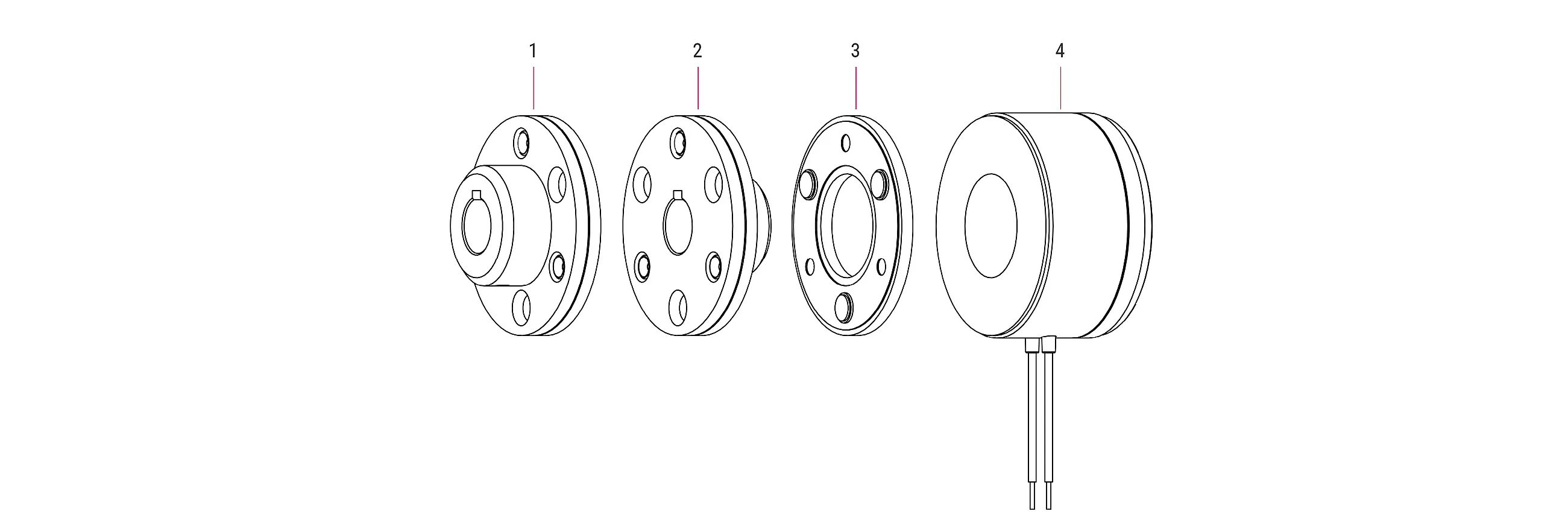
1. Armature version 30 2. Armature version 20 3. Armature version 10 4. Magnet
Options

VdS approved documents top quality and optimum reliability of products and services. In the area of safety technology and door and gate drive systems in particular, the VdS seal of approval underscores reliability and builds trust.

The COMBIPERM P1 connection cables and motor cables can be optionally protected by a plate to prevent possible damage caused by the rotating brake components.

To protect the COMBIPERM P1, and therefore the braking torque, against oil leaking from adjacent bearings, it can be optionally equipped with a felt ring.

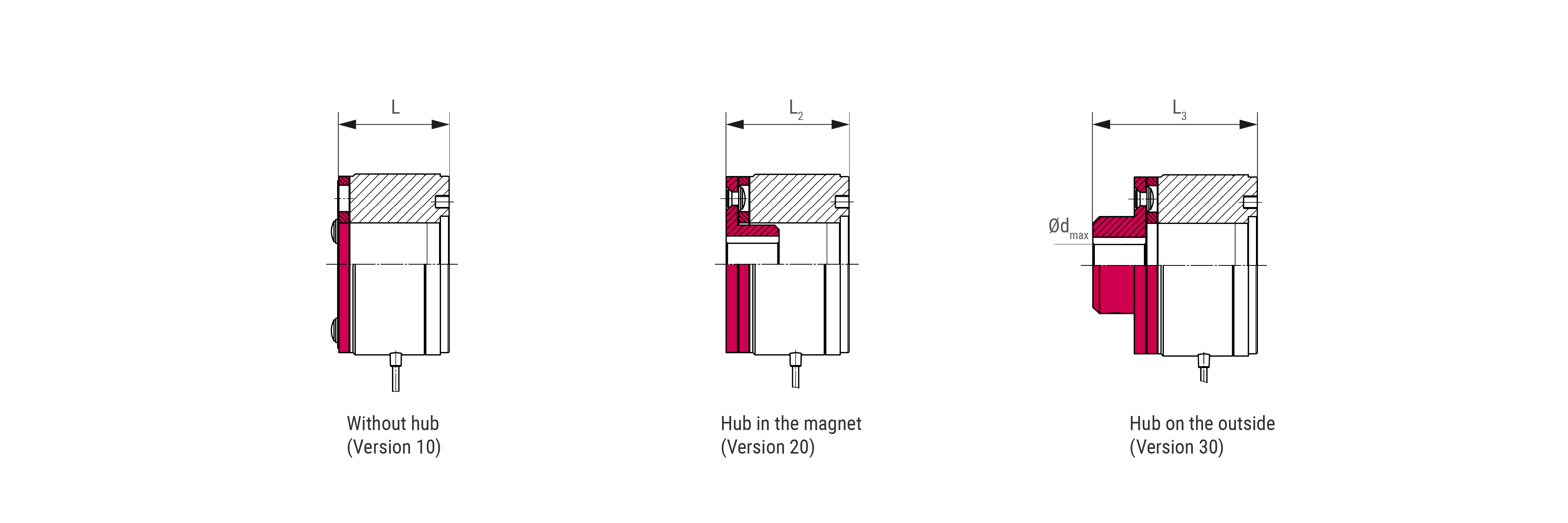
The COMBIPERM P1 design with hub on the outside is the version that is easiest to install (Version 30).
In this case, the armature is attached to the shaft outside the magnet casing.
At the customer’s request, the hub can be designed both with and without a continuous keyway and threaded holes, with threaded pins in the hub.

The COMBIPERM P1 with hub in the magnet is used for a shorter setup than with the hub on the outside (Version 20).
At the customer’s request, the hub can be designed both with and without a continuous keyway and threaded holes, with threaded pins in the hub.

The COMBIPERM P1 without a hub is the version with the shortest axis (Version 10).
In this case, the armature part is mounted directly on the mounting surface, e.g. the pinion, belt pulley or shaft end.
If the application requires a modified voltage, a customised coil with the corresponding voltage can be realised in the internal production process.
If the assembly process of the brake has to be simplified, our products can be equipped with ready-to-connect cables with plugs, contacts or even wire end ferrules.
A factory certificate 2.1 according to DIN EN 10204 that the delivered products comply with the agreements at the time of order can be provided at the customer's request. This certificate is issued based on non-specific testing. Also, an acceptance test certificate 3.1 according to DIN EN 10204 can be issued at the customer's request. In this case, the confirmation is given with the results of specific tests, such as the torque test.

Project solutions
By individually analyzing your requirements and needs, we develop the ideal product for your application.
Benefit from our industry knowledge, our detailed understanding of each component and the interface in the system. This is because our customers and clients are closely involved in every step of the development process, right through to the finished brake. This avoids costly and time-consuming correction loops and results in precisely fitting, high-quality products.
Customer-specific solutions in small batch sizes up to several thousand units per year can be realized. The option of 100% inspections is an important part of our offering for applications with high safety and reliability requirements. The products developed are delivered in accordance with agreed customer specifications.
DOCUMENTATION

Product life cycle
In use in these areas of application
Servo motors
When it comes to servo motors, speed, reliability and flexibility are of the essence. KEB meets these and other requirements with customised solutions. Customers benefit from a servo drive that always stays safely in motion.
MEDICAL TECHNOLOGY
Precision, safety and repeatability are essential in medical technology. This requires solutions that are as reliably produced as the work in the healthcare industry demands. With know-how and established products, KEB has been meeting the high demands in medical technology for decades.
ROBOTICS AND AUTOMATION
In robotics, compactness, repeatability and positioning accuracy are important. Our products meet these criteria precisely and are characterised by their high quality and flexibility. Standard and customised solutions are used by robotics customers all over the world.
INDUSTRIAL TRUCKS & AGVS
Individual solutions, speed and safety are standard for industrial trucks, automated guided vehicles and wheel hub drives. Products from KEB can be individually tailored to the vehicles in intralogistics. Thanks to the many years of experience of the employees, the optimum for the application is brought out together with the customer.
E-MOBILITY
With innovative solutions, KEB enables the electronic operation of auxiliary systems in commercial vehicles and mobile machinery, thereby reducing emissions.
MATERIAL HANDLING
Whether warehouse logistics or cranes, speed and flexibility are essential in material handling. KEB ensures a smooth flow of goods and materials in this area.
VISIT US ON OUR SOCIAL MEDIA CHANNELS:


