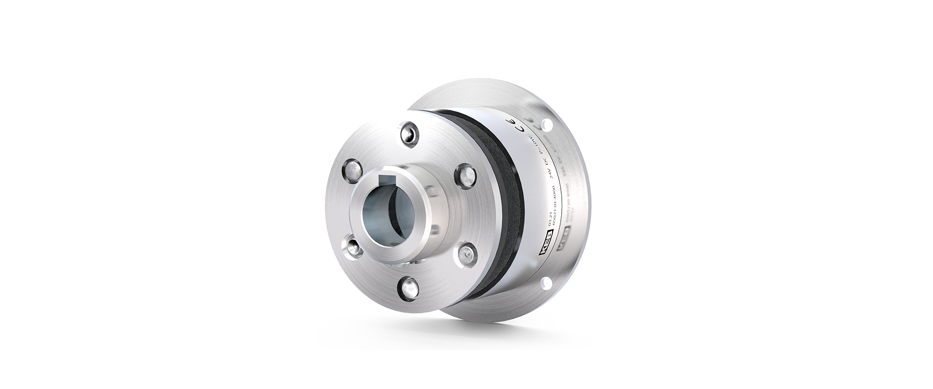
Electromagnetic brake
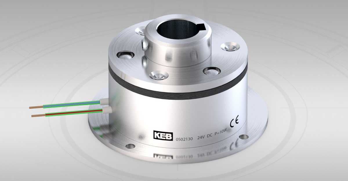
COMBINORM B
The operating current brake COMBINORM B opens when the power supply is switched off or in the event of a power failure. The electromagnetic brake is particularly suitable for precise positioning and reliable holding. It is also used in safety and access technology, e.g. in the area of access barriers or fire doors. The electromagnetic brake is designed for a 100 % duty cycle and can optionally be certified to VdS.
The electromagnetic brake has a torque range of 0.5 Nm to 1,250 Nm.
Highlights
- 13 sizes
- Short switching times
- Positioning accuracy and functional reliability
- cCSAus-certified
- Designed for S1 operation or 100 % duty cycle
- ISO class B in accordance with VDE 0580
- Wide temperature and voltage range
- Continuously adjustable torque
- Standard voltage 24V
DO YOU HAVE ANY QUESTIONS? WE WILL BE HAPPY TO HELP YOU!
Simply send us a message via our contact form.
Contact us nowOptions
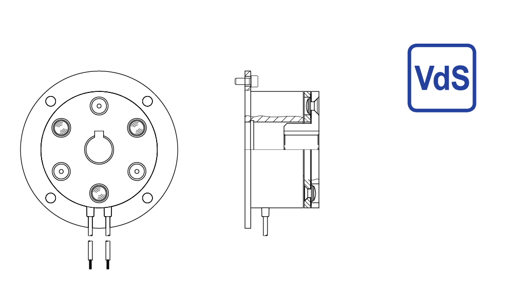
VdS approved documents top quality and optimum reliability of products and services. In the area of safety technology and door and gate drive systems in particular, the VdS seal of approval underscores reliability and builds trust.
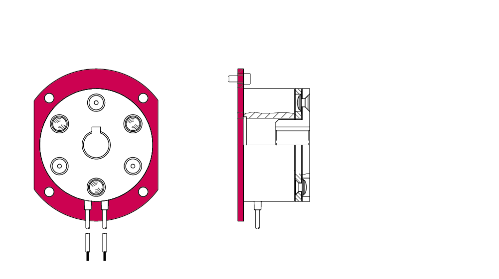
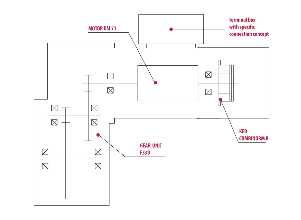
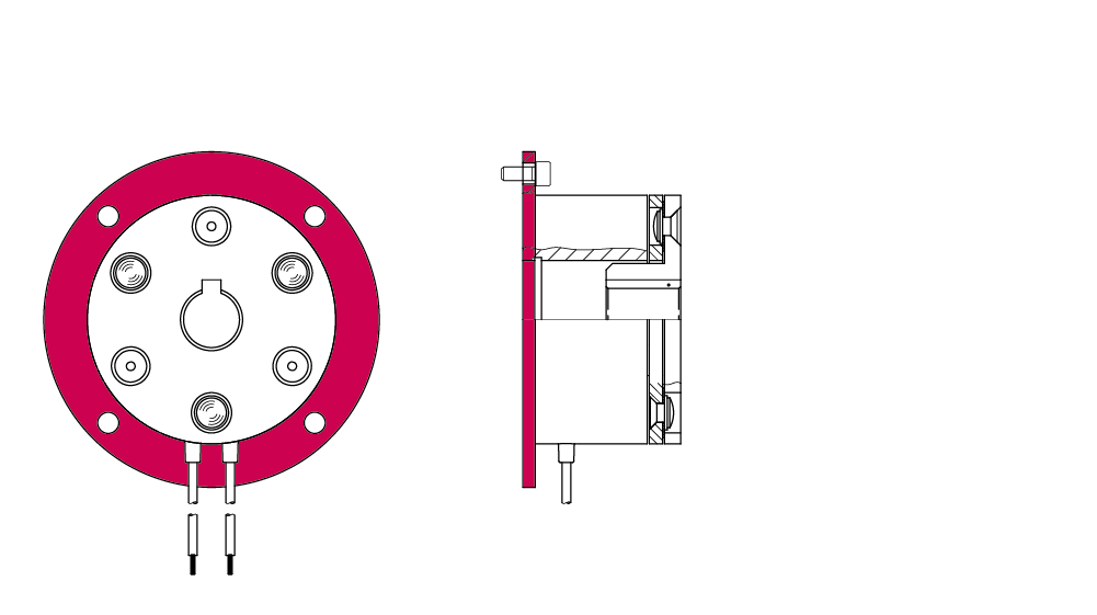
If the COMBINORM B standard flange does not fit the installation situation, it can be adapted in KEB’s in-house production process.
Changes can be made e.g. to the geometry, bore hole pattern, through holes, bolt circle arrangement, mounting slots and a bearing seat recess can be added.

If it is intended that the end products will also be used on the Canadian or American market, the relevant certification can be obtained for the COMBINORM B.
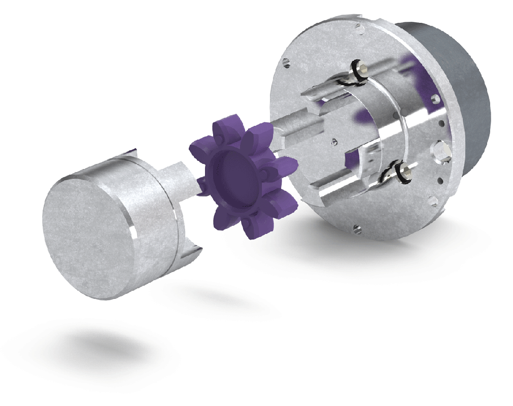
If the COMBINORM B is flange-mounted, the magnet is mounted directly on the mounting surface, e.g. the motor endshield, and the armature is attached to the shaft.
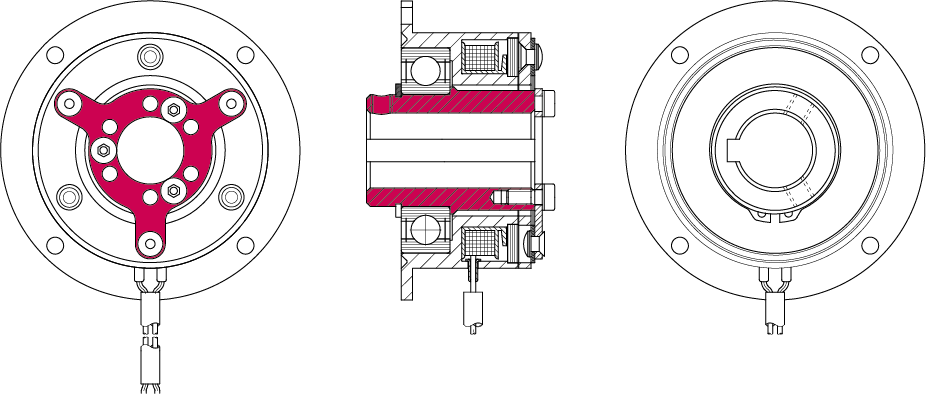
If the COMBINORM B has a shaft-mounted design, the magnet, including the mounted armature part, is secured to the shaft. In this case, the magnetic part is fastened to the housing or bearing assembly via the mounting slots in the flange.
In the process, the magnetic part is mounted on the shaft.
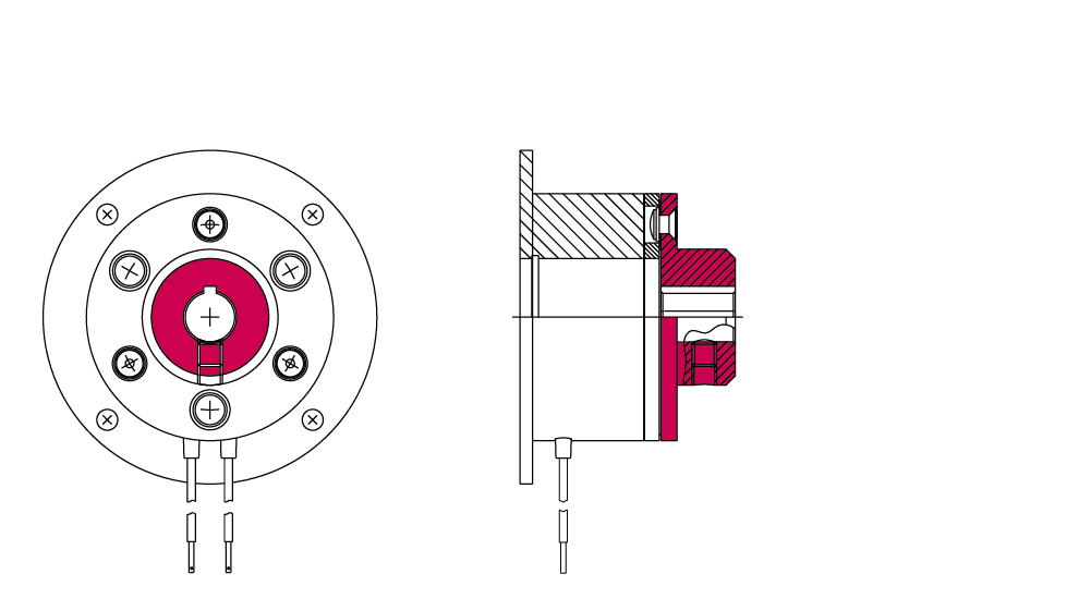
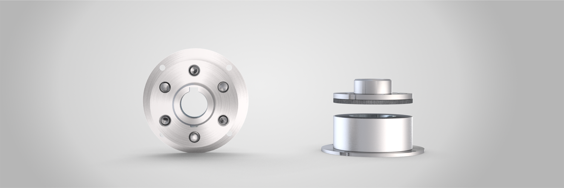
The COMBINORM B version with a hub on the outside is the version that is easiest to install.
In this case, the armature is attached to the shaft outside the magnet casing.
At the customer’s request, the hub can be designed both with and without a continuous keyway and threaded holes, with threaded pins in the hub.
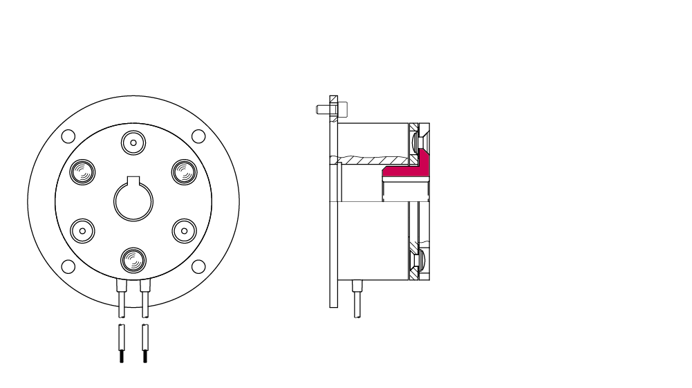
The COMBINORM B with hub in the magnet is used for a shorter setup than with the hub on the outside.
At the customer’s request, the hub can be designed both with and without a continuous keyway and threaded holes, with threaded pins in the hub.
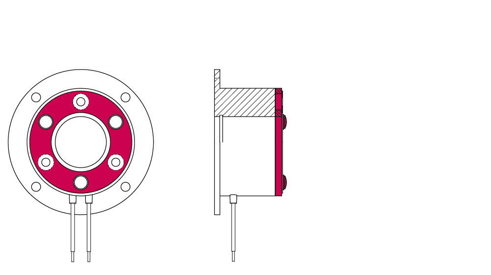
The COMBINORM B without a hub is the version with the shortest axis.
In this case, the armature part is mounted directly on the mounting surface, e.g. the pinion, belt pulley or shaft end.
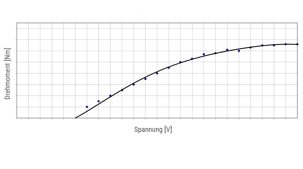
The torque of the COMBINORM B operating current brake can be continuously adjusted by controlling the voltage. An added advantage of this brake is that it enables energy to be saved as the torque depends on the field current and therefore power is also reduced when the torque is lower.
If the application requires a modified voltage, a customised coil with the corresponding voltage can be realised in the internal production process.
If the assembly process of the brake has to be simplified, our products can be equipped with ready-to-connect cables with plugs, contacts or even wire end ferrules.
A factory certificate 2.1 according to DIN EN 10204 that the delivered products comply with the agreements at the time of order can be provided at the customer's request. This certificate is issued based on non-specific testing. Also, an acceptance test certificate 3.1 according to DIN EN 10204 can be issued at the customer's request. In this case, the confirmation is given with the results of specific tests, such as the torque test.
Especially in the case of small brakes, energisation can lead to independent magnetisation, which means that the armature no longer detaches from the solenoid when de-energised.This should be avoided, especially in applications such as fire curtains or safety valves. KEB offers special anti remanence versions of the brake for this case.
If the standard torque of the COMBINORM B is not sufficient, the brake can be produced by KEB as a toothed version. In the case of a form-fit connection, it should be noted that these are designed for static applications and dynamic braking should be minimised.
TECHNICAL DATA
| Size | Rated torque M2 [Nm] | Standard power [W] | Diameter [mm] | max. Hub bore [mm] |
| 01 | 0.5 | 6 | 39 | 6 |
| 02 | 0.75 | 6 | 45 | 8 |
| 03 | 1.5 | 8 | 54 | 10 |
| 05 | 3 | 10 | 65 | 15 |
| 06 | 7 | 12 | 80 | 20 |
| 07 | 15 | 16 | 100 | 22 |
| 08 | 30 | 21 | 125 | 30 |
| 09 | 65 | 28 | 150 | 35 |
| 10 | 130 | 38 | 190 | 45 |
| 11 | 250 | 50 | 230 | 60 |
| 12 | 500 | 65 | 290 | 70 |
| 13* | 750 | 80 | 355 | 90 |
| 14* | 1250 | 100 | 440 | 100 |
Standard voltage: 24 V | Special voltage: on request
Rated torque is reached after pairing conditioning of the friction partners
* Quantity dependent project solution
DOCUMENTATION
In use in these areas of application
MEDICAL TECHNOLOGY
Precision, safety and repeatability are essential in medical technology. This requires solutions that are as reliably produced as the work in the healthcare industry demands. With know-how and established products, KEB has been meeting the high demands in medical technology for decades.
DOOR AND GATE OPERATORS
KEB provides optimal solutions for door and gate operators with an extensive product portfolio. From industrial doors such as fire doors to sectional, high-speed or roller doors and access technology. Safety, functionality and complex operating processes are always the focus.
WOODWORKING MACHINERY
From the control system with numerous software features, to the processing of any machine process data and the drive converter, to the motor with gearbox and brake, KEB is the high-performance partner in woodworking.
E-MOBILITY
With innovative solutions, KEB enables the electronic operation of auxiliary systems in commercial vehicles and mobile machinery, thereby reducing emissions.
ROBOTICS AND AUTOMATION
In robotics, compactness, repeatability and positioning accuracy are important. Our products meet these criteria precisely and are characterised by their high quality and flexibility. Standard and customised solutions are used by robotics customers all over the world.
PACKAGING & FOOD PROCESSING
KEB provides the food processing and packaging industry with robust components that are suitable for use in harsh environments.
AGRICULTURAL, MINING AND MUNICIPAL MACHINERY
Smooth operation, even over long periods of time, requires durable and robust components. These should nevertheless operate according to today's Industry 4.0 standards. Intelligent and robust products from KEB ensure operation in the demanding applications.